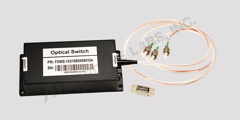
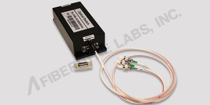
Multi Channel Optical Switch
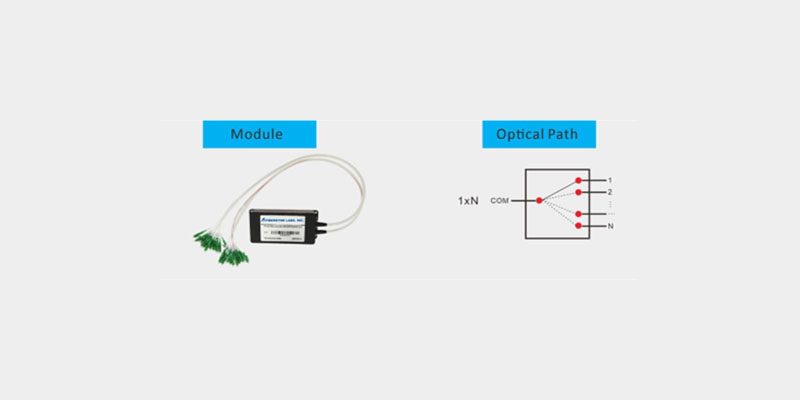
“A 1xN multi-channel optical switch is a device used to control light paths, allowing switching between multiple fiber optic channels. In fiber optic transmission systems, it can be used for channel monitoring, selecting between multiple light sources or detectors, and providing path protection. It is also commonly used in fiber optic testing systems, including component testing, outdoor cable testing, and monitoring multi-port optical sensor networks.”
Technical Index:
| Parameter |
Unit |
1x2 |
1x4 |
1x8 |
1x12 |
1x16 |
1x24 |
1x32 |
1x64 |
1x128 |
| Wavelength Range |
nm |
1260~1650 |
| Testing Wavelength |
nm |
1310/1550 |
| Insertion Loss (Typical) |
dB |
0.5 | 0.5 | 0.5 | 0.5 | 0.5 | 0.5 | 0.5 | 0.5 | 1.0 |
| Insertion Loss (Max) |
dB |
≤0.8 | ≤0.8 | ≤1.0 | ≤1.0 | ≤1.0 | ≤1.0 | ≤1.0 | ≤1.0 | ≤1.2 |
| Return Loss |
dB |
SM ≥ 50 |
| Crosstalk |
dB |
≤ -70 |
| PDL |
dB |
≤ 0.05 |
| WDL |
dB |
≤ 0.20 |
| TDL |
dB |
≤ 0.20 |
| Repeatability |
dB |
≤ 0.02 |
| Lifetime |
times |
≥10⁷ |
| Swiching Time |
ms |
≤10 (Adjacent Channel) |
| Optical Power |
mW |
≤500 |
| Control Mode |
/ |
TTL or Customized |
| Operating Temperature |
℃ |
-10 ~ +55 |
| Storage Temperature |
℃ |
-40 ~ +85 |
| Module Type Dimensions |
mm |
135x64x32 | 135x60x37 | 184x78x66 | 184x156x66 |
|
Ordering Information:
| FOWS- |
XxX |
X |
XX |
X |
XX |
XX |
XX |
X |
| |
Config |
Mode |
Wavelength |
Package |
Fiber Type |
Fiber Diameter |
Fiber Length |
Connector |
| |
1x2 |
S=SM |
85=850nm |
B=Metal Box |
M5=50/125 |
25=250um |
05=0.5m |
0=None |
| |
1x4 |
M=MM |
13=1310 |
S=Specify |
M6=62.5/125 |
09=900um |
10=1.0m |
6=SC/UPC |
| |
1x8 |
|
15=1550 |
|
S9=9/125 |
S=Specify |
S=Specify |
7=FC/UPC |
| |
1x16 |
|
83/=850/1300 |
|
S=Specify |
|
|
A=FC/APC |
| |
1x32 |
|
35=1310/1550 |
|
|
|
|
B=SC/APC |
| |
1x64 |
|
S=Specify |
|
|
|
|
L=LC/UPC |
| |
1x128 |
|
|
|
|
|
|
N=LC/APC |
| |
S=Specify |
|
|
|
|
|
|
S=Specify |
|
Pin Configurations
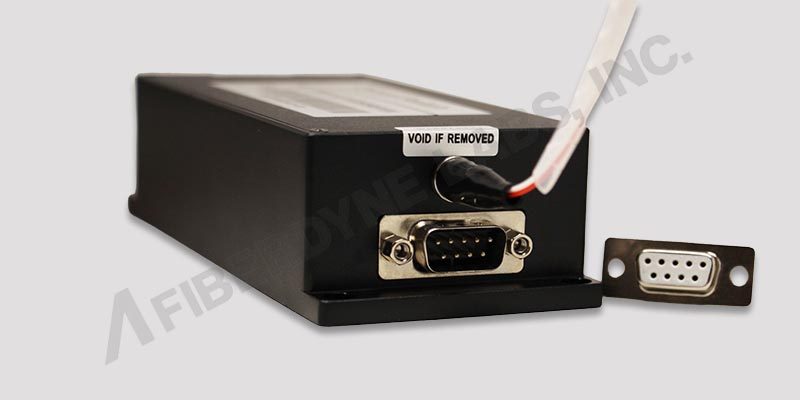
DB-9 Male Connector (1xN≤16)
| DB-9 Male Connector |
| Pin No. |
I/O |
Signal |
Description |
| 1 |
Input |
D0 |
D0~D3 is channel selection Bit0~Bit3. D0 is low, D3 is high |
| 2 |
Input |
D1 |
| 3 |
Input |
D2 |
| 4 |
Input |
D3 |
| 5 |
Input |
Reset |
TTL, Low level reset to channel 0.
High level means channel selection bits are effective. |
| 6 |
Out |
Ready |
TTL, Ready (High=Not ready, Low=Ready) |
| 7 |
Out |
Error |
TTL, Error Or Failure (High=Error, Low=No Error) |
| 8 |
Power |
GND |
Ground |
| 9 |
Power |
VCC |
5.0±5% VDC Power Supply (max 500mA) |
|
DB-15 Male Connector (1xN≤128)
| DB-15 Male Connector |
| Pin No. |
I/O |
Signal |
Description |
| 2 |
Input |
D0 |
D0~D5 is channel selection Bit0~Bit4. D0 is low, D4 is high |
| 3 |
Input |
D1 |
| 4 |
Input |
D2 |
| 5 |
Input |
D3 |
| 6 |
Input |
D4 |
| 10 |
Input |
D5 |
| 11 |
Input |
Reset |
TTL, Low level reset to channel 0.
High level means channel selection bits are effective. |
| 7 |
Out |
Ready |
TTL, Ready (High=Not Ready, Low=Ready) |
| 8 |
Out |
Error |
TTL, Error or Failure, (High=Error, Low=No Error) |
| 1, 9 |
Power |
GND |
Ground |
| 12 |
Power |
VCC1 |
5.0V±5% VDC motor power (max 950mA) |
| 15 |
Power |
VCC2 |
5.0V±5% VDC Drive circuit power (max 50mA) |
| 13, 14 |
|
NC |
NC |
|
Control Chart:
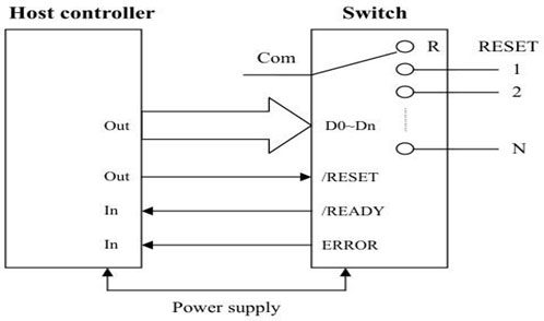
Timing Diagram:
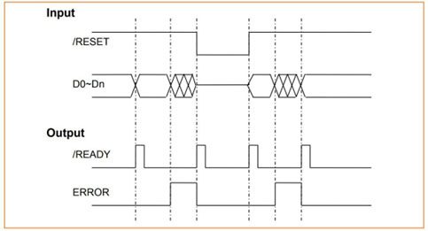
Channel Selection Table:
| Channel |
D0 |
D1 |
D2 |
D3 |
D4 |
D5 |
Reset |
| Com-0 |
x |
x |
x |
x |
x |
x |
0 |
| Com-1 |
0 |
0 |
0 |
0 |
0 |
0 |
1 |
| Com-2 |
1 |
0 |
0 |
0 |
0 |
0 |
1 |
| Com-3 |
0 |
1 |
0 |
0 |
0 |
0 |
1 |
| ..... |
|
|
|
|
|
|
1 |
| Com-126 |
1 |
0 |
1 |
1 |
1 |
1 |
1 |
| Com-127 |
0 |
1 |
1 |
1 |
1 |
1 |
1 |
| Com-128 |
1 |
1 |
1 |
1 |
1 |
1 |
1 |
|
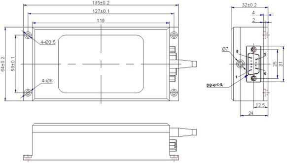
Dimension
1xN≤16 Optical Switch Size: 135x64x32mm
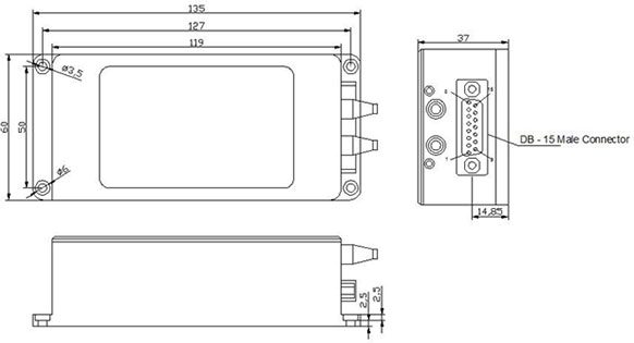
Dimension
1xN≤32 Optical Switch Size: 135x60x37mm
Dimension
1xN≤64 Optical Switch Size: 184x78x66mm
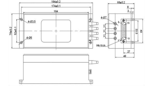
Dimension
1xN≤128 Optical Switch Size: 184x156x66mm
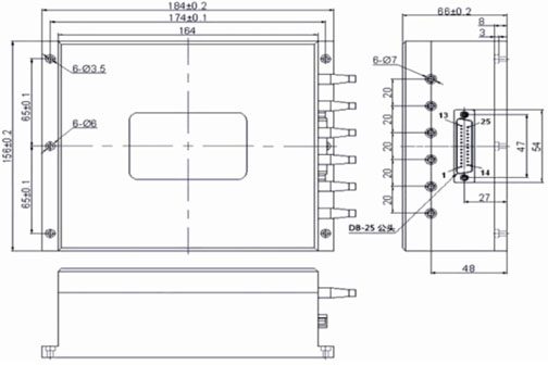
Multi Channel Optical Switch
Fiberdyne Labs, Inc.
127 Business Park Drive, Frankfort, New York
Toll Free: 800-894-9694
Phone: 315-895-8470
Fax: 315-895-8436
Email: